Wednesday, 14 November 2012

The /31 Subnet

/31 Subnet - http://www.ietf.org/rfc/rfc3021.txt

So I'm messing around with my router trying to perfect my BGP knowledge and decided to advertise a network of 210.69.1.1/24 which existed on my loopback 10 interface.

For filtering purposes I needed a longer prefix to appear in the BGP table and I decided to change the mask to /30 but as i was tying the command:


IP address 210.69.1.1 255.255.255.252

I backtracked and thought... what about 255.255.255.254


I've never used this before nor have I seen it on production and technically it should work, after all... loopbacks work with a /32 right?


So lets go for it.


Whoa, look at that warning above, now its getting interesting. Cant imagine anything going wrong but....

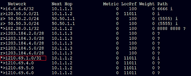
After advertising this network into BGP using the network command it showed up on its BGP peer as expected. All looks good so far.


Lets ping...


Ping works as expected.... so why the warning and why haven't I seen this configured before. Clearly this uses less address space over the /30. After all.. who needs a broadcast on a point to point network anyways? Maybe it's required, I'll have to look into that...

Anyways, so.... what if I configure this on a ethernet segment between two routers using my FastEthernet0/1 using 10.10.10.0 and 10.10.10.1 ? (weird & awesome)


R2 and R8 configured (I'm using secondary because i have an existing IP on there and too lazy to remove it)


And ping test???!!!


Beautiful (Pinging a zero IP is always weird)


Aight lets try this on my ASA... and BAM! ASA doesn't like /31 (I hate firewalls anyway)


Conclusion

Based on a post I read earlier this seems plausible, here' I'll paste:


This probably never caught on with providers because there was no mechanism to roll it out without readdressing your existing customers' circuits. If you are using .0/20, then your usable hosts are .1 and .2, then .5 and .6 in the next block. /31 opens up .0/.1, .2/.3, /.4/.5. . . .If there was a way to keep your existing endpoint IPs and make available p-p circuits of .3/.4, so you could just change masks and then add circuits in the "dead space"


Think, not only of all the customer reconfiguration, but route table overhauls.


It was a good idea in theory.


http://packetlife.net/blog/2008/jun/18/using-31-bit-subnets-on-point-point-links/


Thursday, 8 November 2012

CCIE - written

Written done! woop woop
One more step!

CoPP

CoPP - (Control Plane Policing)

I suffered two days trying to make this work but missed a fundamenal step.

Telnet traffic passing through the control-plane which is destined for another device should have its service-policy set to "Output"

A bit of theory on CoPP
(Taken from - https://sites.google.com/site/amitsciscozone/home/qos/copp---control-plane-policing)

CoPP - Control Plane PolicingDefinitions:
  • Control Plane (CP): A collection of processes that run at the process level on the route-processor (RP). These processes collectively provide high-level controls for most IOS functions.
  • Central Switch Engine: A device that is responsible for high-speed routing of IP packets. It also performs high-speed input and output services for non-distributed line cards. 
  • Distributed Switch Engine: A device that is responsible for high-speed routing of IP packets on distributed line cards without using resources from Central Switch Engine.
          All packets that are destined for CP must pass through the Central Switch Engine before they are forwarded to the process level. The CP and Central Switch Engine are part of the Route Processor (RP).


Overview:

The Control Plane Policing feature allows users to configure a QoS filter that manages the traffic flow of control plane packets to protect the CP of Cisco IOS routers and switches against various attacks like Denial-of-Service (DoS).

The CoPP feature treats the CP as a separate entity with its own input and output ports. Hence a set of rules can be established and associated to the input and output ports of the CP. These rules are only applied if the packets are destined for the CP or they exit from the CP.

Input CP services are executed after input port services and a routing decision on the input path have been made. CP security and packet QoS are applied on-

  1. Aggregate CP Services: An aggregate level by the Central Switch Engine and applied to all CP packets received from all line cards on the router
  2. Distributed CP Services: A distributed level by the Distributed Switch Engine of a line card and applied to all applied to all CP packets received from all line cards on the router.

Types of packets forwarded to CP:

The following L3 packets are forwarded to the CP and processed by aggregate and distributed control plane policing-

  1. Routing protocol control packets 
  2. Packets destined for the local IP address of the router
  3. Packets from management protocols like SNMP, Telnet & SSH.


 Topology above 

R4

interface Loopback0
 ip address 4.4.4.4 255.255.255.255
!
interface Loopback1
 ip address 40.0.0.1 255.255.255.255
!
interface FastEthernet0/0
 ip address 10.20.0.1 255.255.255.0
!
router ospf 1
  redistribute connected subnets
 network 10.20.0.0 0.0.0.255 area 0
 default-information originate

R5

class-map match-any TELNET
 match access-group name TELNET
class-map match-any RATE.LIMIT
 match access-group name RATE.LIMIT
!
policy-map CoPP
 class TELNET
   drop
 class RATE.LIMIT
    police 8000 conform-action transmit  exceed-action drop  violate-action drop
!
interface FastEthernet0/0
 ip address 10.20.0.2 255.255.255.0
 no ip route-cache
 duplex auto
 speed auto
!
interface FastEthernet0/1
 ip address 10.10.0.2 255.255.255.0
 duplex auto
 speed auto
!
router ospf 1
 log-adjacency-changes
 network 10.10.0.0 0.0.0.255 area 0
 network 10.20.0.0 0.0.0.255 area 0
!
ip access-list extended RATE.LIMIT
 permit icmp host 4.4.4.4 host 6.6.6.6
ip access-list extended TELNET
 permit tcp host 4.4.4.4 host 6.6.6.6 eq telnet

R6

interface Loopback0
 ip address 6.6.6.6 255.255.255.255
!
interface FastEthernet0/1
 ip address 10.10.0.1 255.255.255.0
!
router ospf 1
 redistribute connected subnets
 network 10.10.0.0 0.0.0.255 area 0


Saturday, 16 June 2012

CCNP Completed !

Completed CCNP yesterday.
Halfway through CCIE written, happy days, that's all i have to say :)

Sunday, 20 May 2012

STP's Bridge ID

STP, RSTP, MST, PVST all share one common thing which is almost never discusses and rarely documented. The priority value in the BID.

MST - Multiple spanning-tree.
I had to dig to find stuff on this, there isn't a lot of documentation around for MST. A good video that explains the basics can be found here: http://youtu.be/U2CNahYexlg


I'm just off to configure this on my rack and see how things go. 
But back the main topic, STP's BID.
Okay so we know the BID of a switch is the combination of the priority value and the mac address. A normal BID usually looks like this:


The zero is the vlan number, aka system-extended-id used in pvst and rapid-pvst
We’ll come back to that shortly.

We also know how this combination works to determine the root STP bridge:


  1. Lowest priority wins
  2. If priorities are equal then lowest MAC addy wins

But where did this default priority come from? And why does it have to be 32768? A bit weird isn’t it? I didn’t pay much attention to it before, I accepted it for what it was, accepted that it must be for some reason but didn’t care too much. But it really annoyed me when I started tweaking PVST to do load balancing.

In the below figure the following lines were entered on switch A and switch B

Switch-A (config) # spanning-tree vlan 20 root primary
Switch-B (config) # spanning-tree vlan 20 root secondary

Switch-B (config) # spanning-tree vlan 10 root primary
Switch-B (config) # spanning-tree vlan 10 root secondary


Load balancing done for vlan 10 and 20 – beautiful

But as I said before, the priority value is so strange, why the random number, or is it not random?
After some reading I learned back in the old days before PVST the priority value was a flat decimal of 65536, the standard 16 bit number that’s applied to almost everything networking related

PVST uses 12 bits for the system-extended-id leaving 4 bits for the priority value, why?
Well that’s how PVST’s automation works, you see, by stealing 12 bits from the 16 bit value of 65536 we’re able to assign 4096 vlans per priority group… AHHHH so now you see why the maximum vlan range is 4096. Now if you’re wondering what I mean by priority group, I mean the remaining 4 bits.

Confused? Lol

Okay first jump on a switch and enter this:

Switch (config) # spanning-tree vlan 1 priority ?

The output shows you can only go up in increments of 4096

4096
8192
16384
32768

Notice that’s 4 numbers,
Notice the lower number is the usual 4096 seen in vlan configurations
Notice the 32768 is the default priority value for spanning-tree

So it’s not random eh?

This means, as per our diagram, the manual setting of root primary and root secondary respectively which results in 28672 and 24576 must be a calculation of 4096 and yes it is.
They both sit at the power of 7 and the power of 6 respectively


32768 = 8 squared
28673 = 7 squared
24576 = 6 squared
And so on ….

So if you look at it,

The default is 8, setting the root manually drops one increment of 4096, and setting the secondary drops another increment.

Now this explains the randomness, which I guess isn’t random
Side note: if you did your calculations you’d realize the maximum increment is 15 which means you can only set 15 manual spanning-tree bridges in your switch broadcast domain via the priority value.

I suppose you could change MAC addresses, but that’s a bit extreme for STP I would think… what are the chances of 15 bridges failing, and even then if 15 bridges fail I’m sure you wouldn’t give a rats ass about vlan traffic flow, at that point.

Any questions are welcomed

Cheers

Monday, 7 May 2012

NAT / PAT

What a horror!
Encountered a nasty one with Network Address Translation Overload, took me a while to figure this one out.

NAT Overload

The Scenario:
WWW : 209.65.200.241/29
ISP : 209.65.200.254 /29
       : 209.65.200.226 /30 
R1  : 209.65.200.225 /30
       : 10.1.1.1 /30 
R2  : 10.1.1.2 /30
----------------------------------------------------------------------------------------------------------------------------


As you can see, R1 has a public ip address to route on the internet and a private ip address to communicate with the internal network. As we all know RFC 1918 address aren't permitted on the internet so two things needs to be done.

1) NAT/PAT
2) An access list to restrict RFC1918

Here's the config on R1

        interface Serial1/0
         description : FRAME INTERFACE
         no ip address
         ip nat inside
         encapsulation frame-relay
         serial restart-delay 0
         no frame-relay inverse-arp
        !
        interface Serial1/0.12 point-to-point
         description : Link to R2
         ip address 10.1.1.1 255.255.255.252
         ip nat inside
         frame-relay interface-dlci 101
        !
        interface Serial1/1
         description : Link to ISP
         ip address 209.65.200.225 255.255.255.252
         ip access-group 192 out
         ip nat outside
         encapsulation ppp
         serial restart-delay 0
         no cdp enable
         ppp authentication chap

ip nat source list 10 interface Serial1/1 overload
!
access-list 10 permit 10.0.0.0 0.7.255.255 log
access-list 192 deny   ip 10.0.0.0 0.255.255.255 any log
access-list 192 deny   ip 172.16.0.0 0.15.255.255 any log
access-list 192 deny   ip 192.168.0.0 0.0.255.255 any log
 

 So the above config should work right? or so believed
access group blocks RFC1918 addresses out to the internet and NAT overload set for internal clients. It took me hours to figure out what was wrong, combed google, read the cisco NAT / PAT config guide over and over, checked my notes, etc. I started to think maybe this is a bug in the IOS or something.

After clearing my head and troubleshooting from the bottom up, i noticed there were no log hits on the access-list 10 which means traffic wasn't being checked. This is after disabling the ip access-group 192 out on the serial interface to ISP

Turned on ICMP debug on ISP router and to my not-so-supprise i saw the private ip addresses, knociing at the ISP router's door

So, what does NAT and ACCESSLISTS have in common?
Why would the router route the traffic and not include NAT and ACCESSLISTS in the equation?

Answer = our good old friend CEF (Cisco Express Forwarding)
CEF is brilliant for bypassing the route processor and forwarding frames at wirespeed via hardware

So i quickly jumped to my console and typed "no ip route-cache"

        interface Serial1/1
         description : Link to ISP
         ip address 209.65.200.225 255.255.255.252
         ip access-group 192 out
         ip nat enable
         no ip route-cache
         no ip route-cache cef
         encapsulation ppp
         serial restart-delay 0
         no cdp enable
         ppp authentication chap

And NAT in worked beautifully.
I also learned the old way of using

"ip nat inside source list ...."
"ip nat inside"
"ip nat outside"

can be replaced with

"ip nat enable"
"ip nat source list...."

https://learningnetwork.cisco.com/thread/26212

So there it is folks

Introduction

Spent the last 10 years in the server world with some network knowledge and like most server engineers / MCSE / MCITP folk, i thought i knew it all. Yes sir i can ping and i can sub-net and i can do port forwarding, i even know all the well known ports, oh by the way did i tell you i can tracert -d and pathping? and don't make me buss out the angry-ip-scanner.
So i decided to tap into add a few Cisco certifications to the list, namely CCNA, ah yes the feared CCNA.
Obtained it in 2009 but man did it nearly skin me alive. I didn't know networking, i knew jack shit.
3 years after, looking back it, how did i ever think that was hard? and even more important, why did i stay in the server / Microsoft world for so long? Networking is so awesome!
Anyways, here i am, CCNP finishing up and preparing for CCIE R&S
This journey is going to be EPIC!

-------------------------------------------------------------------------------------------------------------------------

Alright so i'm finally finishing up CCNP with TSHOOT exam scheduled for June 15th and getting started the CCIE R&S track. This is going to be exciting
While searching online for information, study tips, rack equipment etc i came across many blogs from engineers pursuing their CCIE detailing what horrors they went through while studying / taking the lab, practical stuff, home labs and work experience. So why not, I might as well join the group =)